Project contents
Robotics
Self-balancing robot
A two-wheeled robot built to learn robotics
- stm32
- c++
- embedded
- robotics
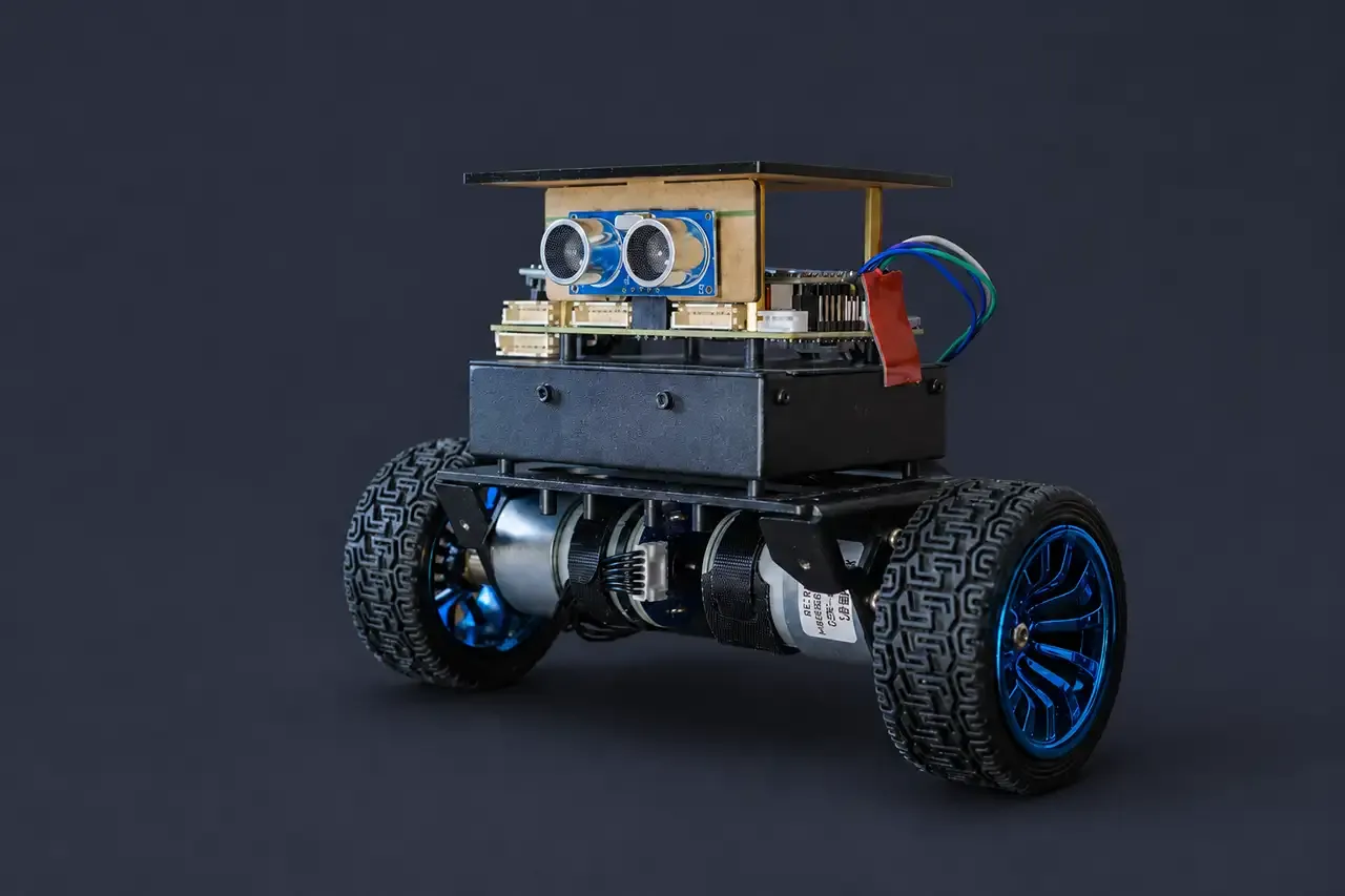
This project started with a Yahboom self-balancing car kit. After playing around with it and working through some of the supplied tutorials, I decided to turn it into a larger project that I could learn more from.
I have never found strictly following tutorials to be the best way for me to learn. Instead, I decided to replace most of the original C application and board-support code with C++. I normally work with Python and TypeScript, so this gave me a reason to get more experience with modern C++ on an actual embedded system. Rebuilding the firmware has also helped me understand the complete path from an IMU packet to a motor command, while keeping the original project as a reference whenever something goes wrong.
My longer-term plan is to add a Radxa Q6A for vision, path planning and voice interaction. I had originally planned to use a Raspberry Pi 5, but the prices became difficult to justify, so I decided to give the Q6A a go instead. It will send movement setpoints over UART while the STM32 handles the real-time balance loop.
This project also has a Build it yourself section for anyone who would like to try something similar. The robot is not finished and does not balance unassisted yet, but the C++ firmware now reads fresh IMU packets and drives both motors in the correct direction during restrained tests. I will continue updating the walkthrough whenever I complete a major feature or milestone.
Where it is at right now
The car does not balance unassisted yet, but here is what is working, what is currently in development, and what I have planned.
Working now
- The complete restrained signal path: a fresh MPU6050 DMP packet reaches the balance controller, which commands both motors in the physically correct direction
- One control implementation running against both the STM32 hardware and a simulation physics model
- A GCC firmware build that flashes over ST-Link/SWD, with a second compiler building it in CI
- Fresh-sample gating, so a rejected IMU poll cannot advance the controller using cached data
- A TIM2 monotonic clock measured at 1.001 against an independent host clock
- Angle-fault hysteresis, observed tripping at about 40 degrees and clearing near 10 degrees
- Eighteen host tests in source. The last recorded complete run passed 18/18 on 22 August; the local host build currently needs reconfiguration before that result is reproducible again
In development
- A stale-data shutdown that writes zero PWM after 25 ms without a fresh IMU sample
- Nine host tests for its deadline, recovery behaviour and 32-bit timer wrap
- A restrained fault-injection test. The measured worst-case IMU poll is 4 ms, but the final zero-PWM evidence still has to be captured
Planned
- Tuning the upright gains and recording the first sustained free balance
- Validating encoder signs before enabling velocity hold
- Moving the control schedule onto the IMU data-ready interrupt and deciding how the FIFO should be drained without exceeding the loop budget
- Enabling turn control once upright and velocity behaviour are understood separately
- Adding the Radxa Q6A as a second compute domain for vision, navigation and voice interaction
Updates
Recent progress
Updates are bullet-point summaries generated with AI from my commits and build notes, then checked by me. Project articles and learning notes are written by me.
-
- Verified TIM2 counts real milliseconds: 6,212 ms on the MCU against 6,208 ms on a PC stopwatch over 63 telemetry lines (ratio 1.001). Cross-checked a second way against the sensor cadence.
- The battery ADC read between 4.96 V and 13.29 V under motor load on an 8.4 V pack, so the measurement is wrong rather than the pack. Leading suspect is ADC sampling that isn’t synchronised with the 25 kHz motor PWM. Not yet confirmed.
- The low-battery cutoff stays disabled until the reading is understood. Averaging more samples first needs a wider accumulator than
uint16_t.
-
- Removed the
delay_ms(5)after each loop. It added 5 ms on top of about 3.34 ms of work, so the loop ran near 120 Hz against a 200 Hz sensor. Motor jitter dropped straight away. - The controller, encoders and telemetry now advance only on a complete fresh DMP packet, because the loop polls 625 to 770 times a second without the delay.
- Added an
IMonotonicClockinterface for the stale-IMU motor timeout. Measured cost: 616 bytes of flash and 8 bytes of BSS, under 1% of the 256 KB flash. - See Run the controller only on fresh samples and Separate the control logic from the hardware.
- Removed the
-
- Confirmed the MPU6050 interrupt is on PA12, not PB12. EXTI line 12 is shared across ports and the port is chosen in
GPIO_EXTILineConfig. PB12 is the PS2 controller’s chip select. Cross-checked by extracting the netlist from the board schematic PDF. - Withdrew a finding that the 1300 motor deadzone needed rescaling. The vendored reference uses the same 2880 timer period, so the deadzone and the PID gains carry over directly.
- Capped the FIFO drain loop at 3 reads (about 2.5 ms) instead of 32 (about 27 ms on the bit-banged bus). Past the cap it zeroes PWM, resets the FIFO and counts the event.
- Found that a failed IMU read leaves the last PWM command latched on the motors, with nothing expiring it. A stale-data motor cutoff has to land before the gains go up.
- Added hysteresis to the tilt fault: it trips at 40° and clears at 10°, so the loop only restarts near upright.
- Confirmed the MPU6050 interrupt is on PA12, not PB12. EXTI line 12 is shared across ports and the port is chosen in